Help to unbrick a TVbox x96 S905x

  • Hello everyone, and thank you for allowing me to participate in this forum. I'll try to be brief so as not to waste your time.

    Today i was trying to revive an old tvbox that when i was a teen I ended up bricking it. If I recall correctly (it was 7 years ago), I erased the entire Emmc card, causing the box only has a red light and no signal. If I connect the box to the PC to try to revive it with the Amlogic tool, it's not recognized by either the Amlogic tool or Windows itself. I know there's a way to short-circuit the Emmc pins for this severe bricks, but it's very difficult for me to find where to do this since it's a Emmc BGA .

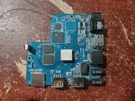
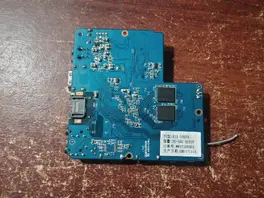
    I was thinking that if I removed the Emmc card (I have a hot air station), the box would enter in the upload mode and I could install LibreElec or CoreElec or something similar on the SD card. Would this be a good idea, or is it a terrible angle? I would appreciate it if anyone has a better suggestion and I have provided photos of the board in case anyone has a backup or something of them.

    Thank you in advance.:)

  • The first thing to do is wire up a UART cable to the board. The pads are in a row of four at the top-right of the board in the upper photo. The square pad is ground, the next two are TX/RX, then +3.3v which doesn't need to be wired. The UART runs at 115200 8/n/1 and allows you to see what happens during boot. Without this you are flying blind and the only response to further posts asking for help and/or saying "that didn't work" is /shrug

    If the eMMC storage is fully erased you can write an AMLGX 'board' image for another GXL/GXM hardware device., e.g VIM1, VIM2, LePotato, etc. to an SD card and see if any of them will boot; first edit the exlinux.conf file to use the p212 device-tree which should work (enough) with any Android box. If the image doesn't boot, try another. The goal is to find an image with u-boot compiled with an acs.bin (which contains RAM spec info) that works with the board. The board has SSV6051P sdio WiFi which is the cheapest of cheap WiFi modules and that normally implies low-spec (low-bin) RAM that's less likely to match against an SBC manufactured with better quality components. Experimenting is free though, and over time I've found quite a few Android boxes that will boot using e.g. LePotato or VIM2 images. If you can boot an image, then you can download the same image to /storage, uncompress it and then 'dd' the image to the /dev/mmcblk1 (eMMC) device and the box should then boot from eMMC again.

    If the board has traces of a wrong u-boot on eMMC (only visible with UART output) then you will need to desolder the eMMC chip to run the u-boot experiments as the bootrom always attempts boot from eMMC first, and the BGA packacing prevents you from doing the normal 'short pins' method (sounds like you figured that out already). The board will then be stuck booting from SD card as resoldering will reinstate the wrong u-boot, but perhaps with the BGA package removed you can see traces and figure out another way to temp short/disable the chip. If you can disable it and boot from SD then you can 'release' the short post boot. The chip can then be detected and becomes something you can erase/overwrite from the console.

    Thanks for sharing your knowledge Chewitt! From what I've seen, you're a master in theses stuff. I'm going to proceed as you said. First, I'll have to get a USB TTL converter. As soon as I get one, I'll post the output logs, since I don't know what they mean.
    Thank you soo much for joinig into the thread.

  • Hi everyone! I'm back with news...:) I got the USB to TTL converter (I had to order it online since I couldn't get it anywhere in my cityX().

    Thanks to a YT tutorial, I was able to setup the converter with the Box, and this is what the PuTTY console shows me in a loop:

    GXL:BL1:9ac50e:a1974b;FEAT:ADFC31AC;POC:3;RCY:0;EMMC:0;READ:0;0.0;CHK:0;

    ERROR! Customer ID not match!

    What that means? For what i understand it's the emmc is empty but i'm not sure.

    There is hope for this old and dying tvbox? Thank you for your time.

  • GXL:BL1:9ac50e:a1974b;FEAT:ADFC31AC;POC:3;RCY:0;EMMC:0;READ:0;0.0;CHK:0;

    ERROR! Customer ID not match!

    The first line is what I would normally expect to see on a GXL (S905X) board indicating BL1 (silicon) cannot find BL2 (software) to boot the board. The second line i've never seen before and my first thought given the wording, is that BL1 is looking for a locked BL2, e.g. in addition to the normal FIP creation process, the boot firmware has been encrypted (signed) with a specific customer key.

    The eMMC is blank though, so you can experiment with e.g. VIM1, VIM2, LaFrite, LePotato, Radxa Zero 'board' images written to an SD card to see what happens on the UART connection. Create the SD card then change the dtb filename in extlinux.conf to meson-gxl-s905x-p212.dtb and see what happens. If any of them run u-boot without experiencing a fail/reset/reboot cycle, you got lucky and the FIP sources for that board will work with your box too. If you see the Customer ID error again BL1 is locked and the only firmware that will boot the board is the original Android ROM that's been signed with the correct key. I have a hunch it's the latter scenario, but the only way to find out is trying.

  • Thanks again Chewitt for your help! I'll proceed as you say. Also i have two questions...

    The eMMC is blank though, so you can experiment with e.g. VIM1, VIM2, LaFrite, LePotato, Radxa Zero 'board' images written to an SD card to see what happens on the UART connection. Create the SD card then change the dtb filename in extlinux.conf to meson-gxl-s905x-p212.dtb and see what happens.

    Do I have to remove the eMMC for do this? Remember, I can't short the pins because it's a BGA eMMC.

    If you see the Customer ID error again BL1 is locked and the only firmware that will boot the board is the original Android ROM that's been signed with the correct key. I have a hunch it's the latter scenario, but the only way to find out is trying.

    If this happens, it means the box is definitely dead, right?;(

  • Post update:

    After trying the many images that you suggested (and change the dtb filename), the PuTTY console output is the same as the one I posted earlier.

    GXL:BL1:9ac50e:a1974b;FEAT:ADFC31AC;POC:3;RCY:0;EMMC:0;READ:0;0.0;CHK:0;

    ERROR! Customer ID not match!

    I don't know if I'm doing something wrong or if this indicates the box is definitely dead.:/

  • It's also possible that ERROR! Customer ID not match! comes from something on eMMC storage, i.e. it's not empty. As I said, it's the first time I see that text so I'm unsure what generates it. Google searching on that exact text generates zero results, which is odd as the GXL:BL1:9ac50e:a1974b;FEAT:ADFC31AC;POC:3;RCY:0;EMMC:0;READ:0;0.0;CHK:0; line has a bunch of hits and IIRC EMMC:0 means it does not see bootable anything there.

    Perhaps go ahead and remove the eMMC chip if you have the tools/skills. At this point there's nothing to loose, right?

  • Yeah I agree with you 100%. I also did not found anything related to ERROR! Customer ID not match!. Maybe (i hope) with removing the eMMC, the box will do something different.
    I gonna try to remove the eMMC with my hot air gun. My skills are not very good because is a new toy but I'll try not to break it more than it is.:D

    Fingers crossed. If I get new results, I'll post them as soon as possible.

  • Post update:

    I removed the eMMC with the heat gun and now when I connect the UART converter I get this output:

    GXL:BL1:9ac50e:a1974b;FEAT:ADFC31AC;POC:3;RCY:0;EMMC:800;NAND:81;SD:0;READ:0;CHK:AA;USB:8;LOOP:1

    This output repeats continuously. The only thing that increments by 1 is the "1" in the LOOP:1 value in each code loop.

    this is happen when an SD card is inserted with the following image: LibreELEC-LePotato.arm-9.0.2.img

    if i remove the sd card the output is similar:

    GXL:BL1:9ac50e:a1974b;FEAT:ADFC31AC;POC:3;RCY:0;EMMC:800;NAND:81;SD:800;USB:8;LOOP:1

    i don't know what this mean but i hope there still a chance to resucite that box

    Edited once, last by Sniperassault: additional info (October 14, 2025 at 2:57 AM).

  • Code
    GXL:BL1:9ac50e:a1974b;FEAT:ADFC31AC;POC:3;RCY:0;EMMC:800;NAND:81;SD:0;READ:0;CHK:AA;USB:8;LOOP:1

    ^ This and no 'customer ID' message is good, it means BL1 is looking for bootable SD or USB media. Experiment with AMLGX board images that (except for the 'box' image) include upstream u-boot, not old LE 9.x images.

  • Hi Chewitt and thanks again for your help! After trying multiple images the best result are with VIM1. With this, it even displays an image on the TV, but it's basically the code displayed by the UART console. The strange thing is that the outputs (whether on the TV or the UART) are always different. I'll attach some, but from what I gather, it always gets stuck on something associated with the kernel.

  • See if https://chewitt.libreelec.tv/testing/LibreE…0.1-p212.img.gz works any better?

    This is not using the VIM1 acs.bin in the u-boot recipe but might work (or not).

    Please use pastebin or similar for sharing logs; it's easer than creating files and uploading/downloading them.

    So sorry fot that! I didn't want to make the post so long and I couldn't think of a better idea than to upload .pdf files.^^


    I tried that image and least now the uart output is ever the same:D. This code repeats in loop while the box is on:

    From what I read in another thread you also participated in, you mentioned that this means the u-boot is partially functional.
    Am I correct, or did I misunderstand?

  • So sorry fot that! I didn't want to make the post so long and I couldn't think of a better idea than to upload .pdf files.^^


    I tried that image and least now the uart output is ever the same:D. This code repeats in loop while the box is on:

    From what I read in another thread you also participated in, you mentioned that this means the u-boot is partially functional.
    Am I correct, or did I misunderstand?

    It looks like a fake s905w SoC (S905W) revision 21:b (a2:2). Since the BL30 complains about "Wrong chip a0."

    This message also appears on an s905l board when attempting to run a standard boot FIP on it.

    An acs.bin for p281 with VIM u-boot should be used here to ensure the 2G of RAM is fully initialized.

  • Thanks bumerc for joining in the thread! I'm new in this stuff and didn't quite understand what I had to do. Should I modify the image I used with some tool or just change the .dtb file? Sorry if I sound silly, but I'm just getting into this world.